Understanding the basic and fundamental concepts of vibration analysis are very important in forming a solid background for analyzing problems in rotating machinery. The change between time and frequency in a tool is a common factor used for analysis because the frequency spectrum is derived from the data in the time domain. The relationship between time and frequency is a very important indicator in the processes of acceleration, speed and displacement. The total vibration energy measured within a specific frequency range includes a combination of all vibration signals within a frequency range measurement and produces a numerical value.
Amplitude vs. Frequency
The vibration amplitude indicates the severity of the problem. The vibration frequency indicates the source of the problem.
Speed vs. Acceleration
Speed is the first derivative of displacement as a function of time, it is the rate of change in displacement (the speed of vibration).
Acceleration is the second derivative of displacement, it is the rate of change in velocity (the change in velocity of the vibration).
When comparing vibration signals in general, it is imperative that both signals are measured in the same frequency range and with the same scale factor.
Vibration Measurement Units
- Displacement (distance) thousandths or micrometers, mm
- Speed (Speed – Displcmt change speed) in / sec or mm / sec
- Acceleration (Speed change speed) G’s or in / sec2 or mm / sec2
Lines of Resolution in Vibration Measurements
Individual vertical lines or containers located adjacent to each other along the frequency axis. Each container is used to store the individual amplitude at a specific frequency location.
Commonly Used Terminology for Machinery Vibration and its Importance in Predictive Maintenance
Here are the definitions of fundamental use for the analysis and monitoring of vibrations with the proper use of the meter or vibrometer:
VELOCITY = Vibration velocity is measured in peak units such as inches per second (ips) or millimeters per second (mm/s). Another way to see speed is distance per time or the amount of movement of the machine each second in three important directions at all major bearing points (AXIAL, VERTICAL, HORIZONTAL).
Speed measurements and vibration monitoring is the most common unit for identifying various problems or acceptability such as: unbalance, misalignment, clearance (machinery structures, foundation or bearings), harmonics and many other problems in the frequency range of the machinery and various multiples of actual speed
Speed measurements (if using a single axis sensor/probe and handheld meter) are recorded in three directions: axial, horizontal and vertical on all main bearing blocks or motor frame end bells.
The advantage over vibration speed is that it is not speed related. Advanced computers with triaxial sensors can measure in all three planes from one location.
The overall or broadband vibration severity used by Velocity is applicable to all types of general rotating equipment (ISO/ANSI) operating at full load or speed conditions. (Exceptions = Diesel engines and rock crushers).
ULTRA LEVELS = .05 ips / 1.3 mm / so less at any speed. No action required.
EXCELLENT LEVELS = .1 ips / 2.5 mm / so less at any speed. No action required.
GOOD LEVELS = .2 fps / 5.0 mm / less at any speed. No action required.
FAIR LEVELS = .3 fps / 7.5 mm / less at any speed. No action is required unless manufacturer’s specifications indicate otherwise, and/or there has been a history of problems on a specific machine (Numerous repairs). The speed of .3 ips / 7.5 mm / s is typically the maximum tolerance level of BORDERLINE in any radial, axial or shaft direction. In many circumstances it may be too costly or impractical to attempt to reduce the vibration velocity below .3 fps / 7.5 mm / s in all sensor directions due to a variety of problems with: Structural or support base weaknesses, system turbulence, stress sensitivities, poor insulation or grounding, poor / incorrect / worn drives, difficult to balance anymore, very hot applications, deformed parts, etc.etc.
GROSS LEVELS = .4 ips / 10 mm / so higher at any speed (Acting soon).
MEDIUM LEVELS = .6 ips / 15 mm / so higher at any speed. (Take measurements now.)
DANGER LEVELS = .8 fps / 20 mm / so higher at any speed. (Shut down and repair)
The relationship of the above vibration velocity levels can be found in the Vibration Gravity Graph. It is important to understand that the vibration can be smooth in one or more directions, but very rough in another, so it is important to record the speed in three directions at each bearing location and preferably within a few hours after start-up.
ACCELERATION = Acceleration data is very important for the detection of bearing failures, gears or electrical problems.
Acceleration is measured in units of G. Simplified = inches per second/second (ips/s) or millimeters per second/second (mm/s). Acceleration is very important in bearing and gear failure data in the high frequency ranges.
Acceleration is also a sudden change in speed. Acceleration data is relevant only on the axis of rotation. Some vibration meters have a headphone output to allow the analyst to hear noise inside the bearings while recording G.
Listening to the bearings using headphones like an electronic stethoscope is very useful for defect identification. Ultra Sound Analyzers can also be used for various tests.
Typical acceleration data related to all types of bearings in general rotating equipment. (Exceptions = Diesel Engines and Rock Crushers)
EXCELLENT LEVELS = Generally .10 G or less. No action required.
GOOD LEVELS = Generally .35 G or less. No action is required unless it is noisy.
FAIR LEVELS = Generally .50 G or less. No action is required unless it is noisy.
(If you do not have records, consider vibration spectrum analysis for all levels below.)
GROSS LEVELS = Generally .75 G or more. Possible action required if noisy. Also check bearing temperature.
MEDIUM LEVELS = Generally 1.0 G or more. Further analysis required. Also check noise and bearing temperatures.
DANGER LEVELS = Generally 1.5 G or more. Probable Problem Further analysis and verification of noise and bearing temperatures is required.
BREAKDOWN LEVELS = Generally 2.5 G or more. Turn off and fix now! Dangerous!
Note: Actual G = 32 ft / sec / sec = 9.8 m / s / s. The vibration equipment converts these values.
As mentioned if there is unusual noise, either audible or with a stethoscope, the acceleration levels G are secondary. This means that there could be an early warning of a bearing defect at the .1 G level.
Turn off the machine and listen carefully to all directions as you go down the coast. If the engine bearings are noisy, repeat this test with the belts removed or the coupling disconnected.
Run the motor at full speed, then turn it off and listen. While the motor is locked, and the drive (belts or coupling disconnected), check that the rotor shaft is not slack by applying pressure in the vertical or axial directions to evaluate excessive play. Rotate the shaft by hand a few rotations and listen carefully for unusual bearing noises.
DISPLACEMENT = Displacement is measured in mils peak-to-peak units (1 mil = .001 “) or mm (1 mm = .0025”). Displacement measurements are recorded in the same three directions as velocity = axial, horizontal and vertical.
Displacement is not used or recommended for recording or monitoring because gravity or acceptability is dependent on velocity.
Displacement is also used to identify problems in the lower frequency ranges. Displacement can be used to measure reference values = walls, floors, beams, pads, frames = very slow or stationary objects.
A conical aluminium probe can be used to measure axial movements of the axis. A Fish Tail shaft rod can be used ™ to measure curves or misalignment with the machine in operation.
For example, 1 thousand at 1800 rpm = Excellent. But 1 mil at 30,000 rpm is dangerous. Typically, dynamic balance tolerances of the rotor are often specified in the displacement (mils) because it has been an industry standard for 60 years or more.
Other balance tolerances are grams/centimeters or tables of degrees of tolerance. Typically, displacement is used in shop and field balancing procedures. For more information on tolerances / degrees of balance, see: The practical application of ISO 1940/1.
FREQUENCY = Frequency is measured in units of cpm, Hz, Orders, i.e. 50 cpm – 750,000 cpm. Knowing the frequency of vibration peaks helps to identify potential sources.
Frequency is used in advanced vibration analysis to identify all types of bearing failure frequencies, real-time spectra and motor current signature analysis, etc.
PHASE = Phase is the vibration angle problem. Phase is used to dynamically balance and identify resonance (critical speed) problems.
Phase is not used in daily vibration measurements or monitoring. The vibration phase is recorded using a stroboscope or an infrared tachometer along with a vibration analyzer instrument. New technologies and software are being used to add phase analysis to the final evaluation and diagnosis.
The Most Common Causes of Bearing Damage or Complete Machinery and Equipment Failure: Based on 40 Years of Experience
1) Incorrect installation. The bearings must be installed and aligned correctly in three directions using machinist levels and other precision tools to maximize life and control vibration. In electric motors, the bell housing and shaft adjustment are critical. The bearings must be properly locked on the shaft (concentric locking collars or locking nuts / rings). Shafts must also be within tolerances (not under or over dimensioned) and undamaged where the bearing is located. New bearings should never be installed in old / worn out blocks. Always replace the entire kit. There is an industry that says = .0005″/ .0125 mm in size that can kill bearing life. In engine applications, the two inner races of the bearing must be heated to exactly 110° C to expand and then coupled to the shaft journal for a perfect fit. Be sure to clean the bearings on the motor shaft or the flanges of any burrs with a fine file and use an emery cloth to smooth the surface of all roughness before installing the heated bearing.
2) Misalignment of units. Precise alignment is very important to reduce vibration and prolong the life of various parts. Check the coupling manufacturer’s specifications and comply with the use of double-quadrant gauges or laser alignment. Remove belt guards during belt tensioning and check with level, straight edge or laser to ensure pulleys are within tolerances at all times.
3) Belts too tight and/or too loose. Proper tension must be maintained at all times. Defective belts should be replaced as soon as possible. Modification to improve the drive system if necessary. Check for serious wear within the pulley grooves.
4) Incorrect lubrication or worn seals causing contamination too much or too little grease. Most good quality EP 1.5 – EP 2 grease on the market is acceptable, but synthetics are the best. Lubrication charts are available for the manufacturer’s machines. If greases are mixed, the laboratory test is compatible. NOTE: On heavy machinery, such as large HP hammers or rock crushers, you should contact the manufacturers to get the best grease to use.
5) Rotor unbalance. As this problem should be obvious, it is usually solved at the beginning. If vibration occurs suddenly in a machine, check for wear, debris build-up, broken or cracked parts in the rotor. Unbalance in a variable speed machine usually appears as a gradual increase in vibration as the speed increases and the highest at full speed. VIBES Corp specializes in dynamic rotation of parts on site.
6) Vibration for a long time. Sometimes sudden vibrations can be overlooked because the machine has always run that way, i.e. harmonics, heartbeats, resonances, transient vibrations, bending supports, aerodynamic turbulence, pump cavitation, misc. On axial fans, check for “Stagnation” or on pumps check for cavitation. Axial fan “stall” is due to increased resistance at the inlet or outlet and can be caused by problems with dirty dampers, filters or coils, defects in fan blade modulation and other system problems. “Surge” is the same as “Stall”, it only refers to centrifugal fans. During “Fan Stall”, usually near or at full speed, there may be a problem with the dampers not opening or clogging the filters at the inlet. That resistance can cause “Surge” and you may notice extreme axial vibration or inertia pad rebound.
7) The engine is operating beyond the full load amperage caused by excessive speed in the drive. Check the pulley ratios, use the amplifier probe, tachometer, or stroboscope to confirm that the driving speed is a problem.
8) Poor or no isolation. Check the springs for grounding, too much deflection, or incorrect selection. Axial vibrations in fans can often be reduced by using thrust springs. Pump or pipe vibration transmissions can be reduced with expansion joints, flexible hoses or spring hangers.
9) Bearing contamination. Driven machinery bearings that are in hostile environments such as vertical shaft cooling towers, exposed to the elements, gas/moisture mixture or heavily soiled areas can become contaminated if they are not protected by special seals, cooling discs or shaft assembly protectors. Care must be taken not to over-grease the motors. Motors should also be protected with silicone around the faces of hoods and cable boxes if exposed to high humidity areas.
10) Poor or incorrect bearing selection. Sometimes, when bearings are replaced, the new bearings do not have the same load as the original. The bearings should always be the same size as the original and if they consistently fail, consider upgrading the bearings with a higher dynamic load. Large HP motors in belt drives should have roller bearings at the drive end and fixed ball bearings at the opposite end.
11) Electrically induced bearing damage (EIBD). Motors operating at 460V and 575V with VFD can often develop this problem which is caused by voltage build-up in the rotor and the discharge of milliamps (micro-arc) through the bearings back to the stator. The result is noisy pitting, glazing, scoring, micro-cracking and cratering of the rolling elements and ducts along with burned/contaminated grease. There are several solutions to prevent or combat EIBD problems depending on the circumstances and budget, such as:
a) DE / ODE motor bearings sealed with electroconductive grease
b) Rotor grounding ring/ring
c) Sine wave filter
d) Ceramic sleeves
e) insulated bearings
f) Loading coils and lateral electric shock absorbers
A more detailed article has been written and is available on our website: see Know the Axis Currents / EIBD. See the vibration acceleration spectrum showing a serious EIBD problem here.
12) Resonance is when the rotation speed and natural frequency are close or exactly the same. You will notice a sudden and significant increase in vibration at the resonance. When converting a constant speed machine to a variable frequency drive (VFD) or an adjustable speed drive (ASD), you must run the machine slowly to identify any resonance in the entire speed range. If you notice resonance, you can try these four steps to control or eliminate it as follows:
In the VFD or ASD program, electronic signals avoid that speed/frequency. The resonance can be present through a 1 Hz change in the speed range usually above 45 Hz.
Add parts to harden the machine. If further testing is required.
Add mass to the machine. Further testing is required.
Change the driven speed ratio by -10% -15% for a constant speed machine.
13) Soft Foot: The soft foot has been found to cause significant increases in vibration usually in the motor. This problem should have been identified and corrected during alignment. To find problems with soft feet, try these two steps:
Using the live display on your laser aligner or vibration analyzer (while the machine is running), undo one motor foot bolt/nut at a time and see if there is a difference in the data. Tighten each bolt/foot nut before undoing the next one and so on.
Same test as above but using a dial indicator to record the data for four feet (while the machine is on/off).
Fact: a soft foot up to +.002″ can cause a difference in vibration from rough to good. The soft foot can also be the source of a high vibration peak at an electrical frequency of 7200 CPM but much lower at 1x RPM. Stress on the stator frame when there is uneven contact on all four feet of the motor. The above tests will confirm if it is a soft foot.
Important: Vibration data should be recorded in the same direction and location of the point sensor when the machine or motor is running at the same load/speed each time or the trend may be useless or confusing. If maximum speed is not possible, record at the same lower speed each time.
Typically, 80% speed or fan blade angles are satisfactory for vibration monitoring and trending (100% speed or full load condition is best for monitoring and evaluation).
Related Topics in ALPHAPEDIA

💚 WALL LAMPS MODERN: Great Price on Qualified Products
💚 WALL LAMPS FOR BEDROOM: Great Price on Qualified Products
💚 WALL LAMPS: Great Price on Qualified Products

HOW ELECTRICITY IS GENERATED ?

CARTOON FIREPLACE Decorated and For Christmas: How to Make Them ?
ELECTRICITY STUDY OBJECTIVES

USE OF VOLUMETRIC FLASK

CAPACITOR: Definition, Types, Uses and Prices

NUMAXES SCALE: Prices and Offers
Other Topics of Interest in ALFAPEDIA

FREE TOURISM BACHELOR DEGREE

ROMAN GODS: Names, Meanings and Characteristics

FREE PhD IN ENGLISH

FREE TATTOO ARTIST COURSE
FREE ASSISTING IN HOME CARE COURSE
FREE BACHELOR DEGREE IN SOCIOLOGY
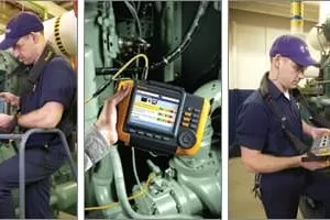
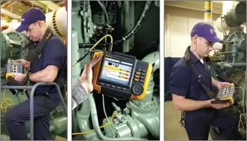
Vibration Analysis Image